CFC-400 type layered sedimentation instrument
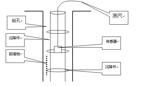
CFC-400 type layered sedimentation instrument working principle: The sensor used in the layered sedimentation device is designed according to the principle of electromagnetic induction. The magnetic induction settling ring is pre-buried into the underground to be tested at various points through the drilling method. When the sensor passes through the magnetic induction ring, an electromagnetic induction signal is generated and sent to the ground instrument display. Sound and light alarm. Read the scale value of the corresponding steel ruler on the hole mark point, which is the depth of the settling ring. The amount of settlement of each measurement is subtracted from the previous measurement. 2 Measurement method: Graph 1 graph 2
Key words: layered sedimentation, stratification 
First, the application area:
The CFC-400 layered settler is an in-situ tester for ground-based monitoring. It is used for foundation pits, slopes, dams, and foundations to monitor the settlement of different layers in the deep. Through the change of test data, the settlement trend is calculated, the stability is analyzed, and the construction process is monitored. It is one of the important instruments for engineering monitoring units and simulation experiments in colleges and universities.
Second, technical indicators
1. Probe size: length 200mm, diameter φ35mm;
2. Measurement accuracy: ±1mm, manual recording;
3. Measurement range: 0°~±50m; test depth up to 100m;
4. Working voltage: nickel battery +12V;
5. Working temperature: -10 ° C ~ +60 ° C;
The probe structure is firm and the sealing is good. The steel ruler cable is integrated, the whole machine is portable, light in weight and powered by DC power supply, suitable for various field environments.
1. Drill the hole of 90mm, embed the settling pipe into the hole according to the design depth, press the set ring with the plastic pipe with the inner diameter larger than the settling pipe into the hole to measure the depth of each point, and fill the sand with water to compact it. one)
a Orifice elevation method. Make a mark on the orifice, and the test should be based on the mark. The height of the orifice is measured by the measuring instrument (this method is commonly used).
b Hole bottom elevation method. Taking the bottom of the hole as the reference point (provided that the settling tube should fall to a relatively stable point in the ground), test from point to top point by point.
3. Ground instrument operation method (1) Before testing, turn on the instrument power switch, and use a settling ring to cover the probe movement. When the settling ring encounters the sensing point of the probe, it will sound and light alarm, and the instrument has instructions to indicate the instrument work. normal.
(2) With the orifice (or bottom of the hole) as the elevation, the probe is placed into the probe. When the sensitive center of the probe intersects the settling ring, the instrument emits a “beep†sound, accompanied by a light indication, and the meter indicates that the value is simultaneously large. . At this time, the indicated value of the steel ruler at the reference point is the depth value of the settling ring. Comparing the test values ​​(ie, the difference) for each time, the settlement at different depths can be obtained.
(3) After the test is finished, turn off the power and wipe the steel ruler for reuse.
(4) When the alarm sound is small or silent, it indicates that the electricity is basically exhausted, and the battery should be replaced in time. When changing the battery, please pay attention to the positive and negative polarity, so as not to damage the battery.
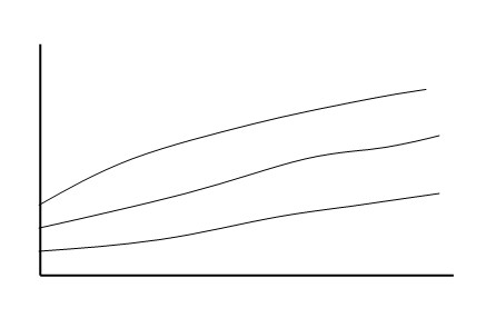
5. Data compilation After each point is buried, a stable initial value should be measured, generally 2-3 times, and a stable initial value is obtained. The difference between each test value and the initial value is the settlement value Δh at that point.
According to â–³h=h measured-h initial According to the value of â–³h and time t, the curve of settlement with time can be drawn (see Figure 2).